The last few years have seen an increase in adoption of the USB Type-C connector. It has simultaneously been accompanied by additional technological innovations on top of it. This has created a need for devices and tools to monitor the communication over the connector – in particular, the power delivery (USB-PD) aspect. While costly USB protocol analyzers fulfil the requirement of companies involved in silicon development and low-level hardware, these are impractical for people looking to optimize their microcontroller projects, hobbyists, enthusiasts, and even end users.
The Google Twinkie (developed in 2014) was the original USB-PD Sniffer. Since then, many devices have attempted to replicate at least some of the functionality in a more user-friendly manner. However, none of them were able to match the Twinkie’s flexibility for advanced users. Unlike the Twinkie, the designs also interfered with regular data traffic while monitoring the power transfer. ChargerLAB’s KM003C is one of the latest premium solutions in the list, and it ticks many of the boxes that other solutions do not. In fact, it goes one step further than the Twinkie by supporting the EPR specifications also (Extended Power Range, up to 240W).
One of the key advantages of the Google Twinkie is the availability of a shell over a serial port through which the operation can be configured. This allows end users to develop custom scripts and applications for tracking various parameters. At AnandTech, we have been using Plugable’s USBC-TKEY (a version of the Google Twinkie for the retail market) to track the power consumption profile of bus-powered USB devices since 2016. After 7+ years of service, the USBC-TKEY had started to show its age, prompting us to be on the lookout for an alternative. After looking at the specifications of the ChargerLAB KM003C, we decided to take a punt and purchased one to see if it could replace the USBC-TKEY in our workflow.
ChargerLAB provides a Windows-only closed-source application to expose the advanced features of the KM003C (beyond what is presented in the display on the device). The company also provides documentation for their APIs in Chinese. This review takes a detailed look at the features of the ChargerLAB KM003C. It also details our attempts to use their APIs to replicate the Google Twinkie functionality for AnandTech’s use-case.
The USB specifications have been subject to rapid updates since the introduction of the Type-C connector. Data rates have been increasing and the latest versions even allow encapsulation of PCIe traffic. At the same time, the USB-IF also foresaw the need for flexibility in transmitting different amounts of power from the host to the device and vice-versa. Towards this, the USB-PD (power delivery) specifications were also developed. The latest revision – USB-PD 3.1, brings support for 140W, 180W, and 240W power levels. The PD specifications have also allowed for power transmission either from the host, or the device. All these capabilities are enabled by a power delivery handshake process between the devices on either side of the cable. As the power delivery standards evolve in both capabilities and flexibility, a need has come up in the market for devices that can provide feedback to the users and developers on the PD handshake process and its results.
USB protocol analyzers also include support for analyzing the PD handshake process. Silicon and low-level hardware developers do use them, but they are usually extremely costly (because they also support the tracing and debugging of the high-speed data transfers). The PD handshake process is at a relatively slow speed (around 300 KHz) over the CC (control channel) wire, and doesn’t require high-speed signal monitoring. There are many low-cost devices in the market that tap the CC1 and CC2 pins to provide information on the PD handshake process to the end user.
Power delivery sniffers also need to monitor the voltage and currents on the VBUS and VCONN pins. Advanced sniffers allow for the injection of power delivery packets on the CC pins and also placing the termination resistances. From a power measurement perspective, the interesting ones are the VBUS and VCONN. The former carries bus power for devices (and, in some cases, for the circuitry in the cable itself). The voltage may vary from 5V for typical USB 2.0 hosts / devices to up to 48V for USB-PD scenarios. VCONN, on the other hand, is always set to 5V and can supply up to 1W of power for circuits within the plug. These circuits can implement electronically marked cables or even be accessories.
The pin-out diagram above shows the D+ / D- differential pair that is used only for USB 2.0 traffic. An inline power delivery sniffer could opt to cut out the path, eliminating USB 2.0 data transfer path completely. The same could be done for the TX / RX pairs responsible for the higher speed data traffic in USB 3.x / USB4 / Thunderbolt 3+. While there are some legitimate use-cases for allowing only power transfer via the USB cable, most users employing an inline power delivery sniffer want data traffic to be untouched. Unfortunately, a majority of the low-cost sniffers in the market take the easy way out by completely ignoring the data transfer path.
ChargerLAB KM003C Package Contents and Feature Set
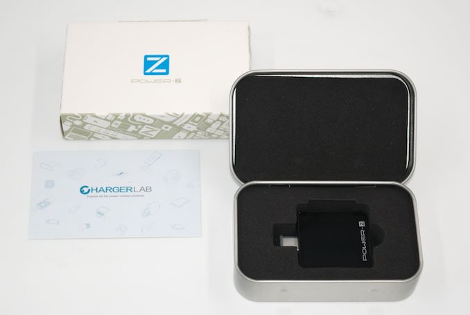
The ChargerLAB / Power-Z KM003C is marketed primarily as a USB PD tester, and comes in a non-descript box. The rear label provides the high-level specifications in terms of supported voltage and current range, as well as fast charging protocols. Contact details for support and business issues are also provided.
Inside the package, we have an aluminum storage box with the PD tester placed inside a foam cladding for protection when the unit is not in use. The Type-C male port also has a protection cap. QR codes with links to ChargerLAB’s YouTube and Telegram channels are provided in an accompanying business card.
The ChargerLAB / Power-Z KM003C is an inline device placed between the downstream facing port (DFP) of a host and the upstream facing port (UFP) of a device. Either component can act as the source and sink in terms of power delivery. It is used for voltage and current detection, power delivery capability testing, cable testing for e-markers, fast charging protocols detection, and other such tests.
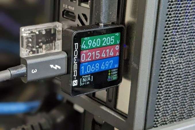
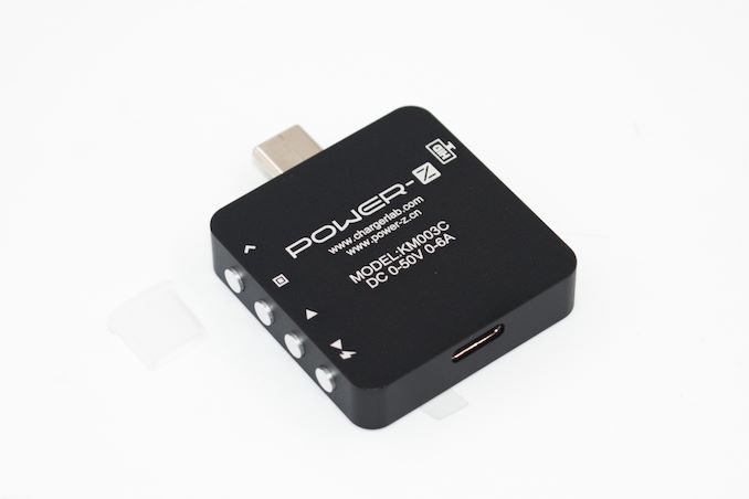
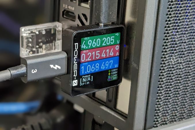
The KM003C itself is a cuboidal piece of aluminum (measuring 36.5mm x 35.5mm x 8.7mm, weighing in at 16.5g) with a Type-C male port as the UFP, and a Type-C female port as the DFP. It is equipped with a vibrant 240 x 240 1.54″ IPS screen that provides real time information on the VBUS, IBUS, power consumption, charging protocol (if applicable), and voltages on different lines in the connector. The product is also equipped with a Type-C HID port that can be used to interface it with a PC for data recording and further analysis. There are physical buttons on the product that allow the user to navigate the menus, configure various testing parameters, set sampling rates, etc.
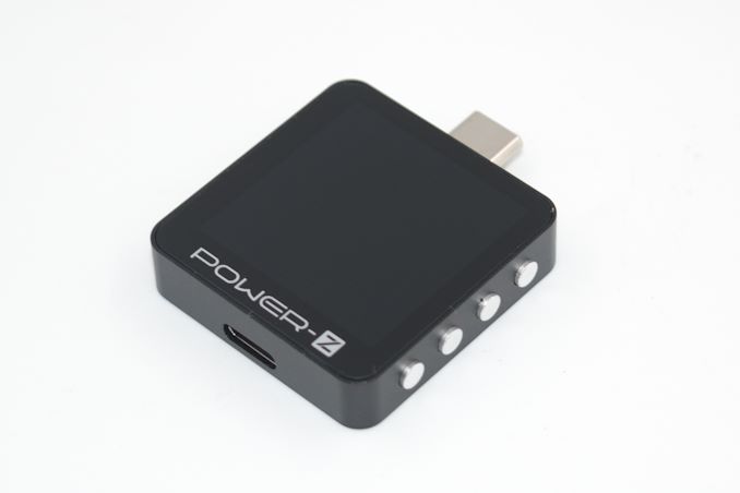 Physical buttons on the KM003C (the HID port is on the face opposite to the buttons)
The KM003C can perform some basic operations with the power supplied via the VCONN line, but it requires connection to power through the HID port for full-fledged operation. The typical power consumption of the KM003C itself is around 75 – 250 mW. It also includes a supercapacitor that allows for a safe shutdown (ensuring that data in flight is flushed out to permanent storage) and the display to remain active for around five seconds after the power is disconnected.
ChargerLAB also bundles a closed source Windows-only software to graph and store the recorded parameters on a PC for further processing.
ChargerLAB KM003C vs. Plugable USBC-TKEY
The Google Twinkie / Plugable USBC-TKEY and ChargerLAB KM003C are conceptually similar in that they are both USB PD sniffers / testers. However, the differences are evidence to the advancements made in the USB space between 2014 and 2022, and also reflect the evolution of end-user requirements in this space.
The key difference lies in the power specifications. The Google Twinkie / Plugable USBC-TKEY can support only up to 20V / 5A on the VBUS lines due to the limitations of the digital power monitoring ADC chip being used. The KM003C can support up to 50V / 6A (full USB-PD 3.1 specifications, with EPR up to 240W).
The use of a more recent ADC chip has enabled increased measurement accuracy in the KM003C as compared to the Google Twinkie / USBC-TKEY. The INA231 used in the latter has a 16-bit ADC and a voltage measurement step size of 1.25 mV. The INA228 in the KM003C has a 20-bit ADC and a voltage measurement step size of around 0.2 mV. The INA228 also includes temperature monitoring (and that is available via APIs and the display screen on the KM003C).
The Twinkie was designed primarily for use with Chrome OS, and as a result, its retail versions such as the Plugable USBC-TKEY support only Linux. TotalPhase offers the TP350110 based on the same hardware as the Twinkie. It comes with modified firmware and drivers that support both Windows and MacOS, along with extended APIs and a custom data processing application at a steep premium. The KM003C supports only Windows officially for the connection through the HID port, and their data processing software is also Windows-only.
The Twinkie / USBC-TKEY has a CLI shell accessible over a USB serial port and comes with support for a specific set of commands (like ‘tw vbus’ and ‘tw vconn’ for reading the voltage and current on the VBUS and VCONN lines, ‘tw res param1 param2’ for placing resistors on the CC lines – Rp / Rd / Ra), etc.). The KM003C is accessible over the HID port and is receptive to commands, but those are custom encodings without an interpretation layer in the middle.
The Twinkie / USBC-TKEY can act as a sink and inject power delivery packets to make the host / source negotiate a different power delivery contract. This is also available in the KM003C when using the cable simulation and charging protocol detection feature, but does not seem to be exposed via the APIs (to the best of my understanding).
The Twinkie / USBC-TKEY can set up or remove resistors on the CC lines in order to configure the connected port as either UFP or DFP. The KM003C appears to have a similar functionality for the Rd alone. Again, this does not seem to be exposed via the APIs.
The next section talks about the hardware design and software capabilities. It is followed by a discussion of the API support and how to use them on both Linux and Windows. After adapting our direct-attached storage flow to support power monitoring from both USBC-TKEY and KM003C, we recorded some results from both meters. We provide some comparisons of those results before proceeding to the concluding remarks.
The internal layout of all USB-PD sniffers is quite similar. A microcontroller acts as the control center (interfacing with the data monitoring host and tapping into the CC lines). Power monitoring ADCs (TI INA family in most cases) are placed on the VBUS and VCONN lines after placing a shunt resistor in the path. These INA chips interface with the microcontroller over an I2C bus. The schematic for the Twonkie 2.0 (a Twinkie clone with updated components that is easier to prepare for DIY folks) is reproduced below.
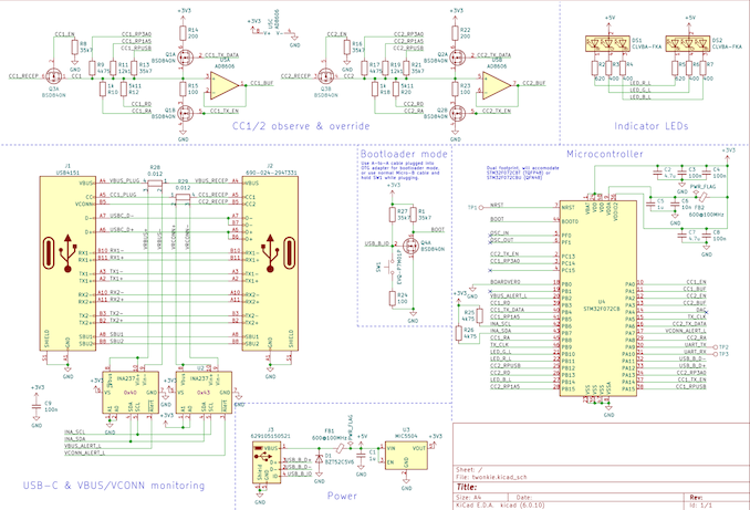 Twonkie 2.0 Schematic – STM32F072 + 2x INA237 + 2x 12 mOhm Shunt Resistors
The Google Twinkie / USBC-TKEY differs only slightly from the above schematic, with 2x INA231 power monitoring ADCs in place of the 2x INA237. There are multiple resistors in the CC observation path, and these enable the placement and removal of the Rp / Ra / Rd from the Twinkie’s CLI. The STM32F072 microcontroller has a Cortex-M0 CPU running at 48 MHz, 128KB of flash memory, and a 16KB SRAM.
The ChargerLAB KM003C’s structure is likely to be similar to the above. Based on the photograph of the KM002C’s PCB (the KM003C is an updated version with a larger screen, gravity sensor, and a supercapacitor), the main differences appear to be the use of a Huada HDSC HC32F460 microcontroller, multiple INA228 ADCs, and 20 mOhm shunt resistors.
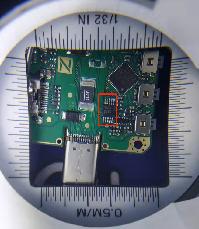 KM002C PCB, with the TI INA228 ADC boxed in red
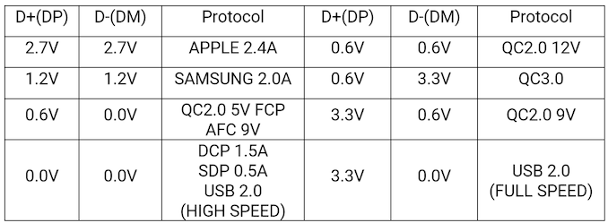
The HC32F460 is a highly advanced microcontroller compared to the STM32F072. It has a Cortex-M4 CPU (with floating point support) running at 200 MHz, 512KB of flash memory, and 192KB of SRAM. This allows the implementation of a fairly complicated user interface with built-in real-time graphing capabilities – features that are not present in the original Twinkie design. We believe that the KM003C includes at least 5 ADCs in order to measure the voltage on both CC lines as well as the D+ and D- lines (in addition to the VBUS). Voltage measurement on the D+ / D- pins is apparently necessary in order to detect and support custom fast-charging protocols, as indicated in the table below from the KM003C’s user manual.
One of the bugs in the KM003C hardware design that has been acknowledged by ChargerLAB is the absence of support for USB 2.0 data passthrough. It is likely that the voltage monitoring on these lines for fast charging protocol detection purposes is breaking the data lines for normal operation. It is an unfortunate side-effect that hopefully gets fixed by ChargerLAB in the next hardware iteration.
On-Device Interface
Moving on to the external hardware aspects, the KM003C is equipped with a vibrant 240 x 240 1.54″ IPS screen and four physical push buttons. These allow the user to navigate through the various on-screen options for activation of different features, and also include special signals to modify certain settings quickly (such as a long press on the ‘Confirm’ button to alter the sampling rate when the dashboard screen is active). The gallery below presents the various features available via the device screen.
After power up (and showing an optional startup image set up through the PC software), the screen lights up with the dashboard that provides important information at a glance – the voltage, current, and power consumption inferred from the parameters on the VBUS line, the charging protocol (if applicable), and voltages on the CC and D+/D- lines. The next interface is the application screen from which the charging protocol support detection can be triggered. This involves ensuring stable power supply through the HID port and connecting the Type-C male port to the power supply of interest. The female port should be left unconnected. Under this option in the interface, it is possible to trigger cable simulation (by selecting ‘No e-marker’), request for a specific PD type (after selecting ‘Auto’), and scan for different charging protocols support. Yet another option under the application screen is ‘Modules’. Under this, various value-adds such as USB-C cable e-marker reading, and Apple charger genuineness checking are currently available. ChargerLAB plans to add testing for cable resistance also in the future.
Under the Settings screen, the display brightness and startup screen can be adjusted. Storage management options are also available. Language settings (Chinese or English) and device information, as well as the option to reset all settings to default can all be accessed from the same screen.
The real-time curves interface allows the user to view the voltage / current on the VBUS line, or the voltages on the D+ / D- lines, or the voltages on the CC1 / CC2 lines as a function of time. The screen also helpfully notes the sampling rate on the top left corner. The data storage interface records the charge and energy values from the INA ADC chip for the VBUS line. The save interval is configurable and the starting and stopping of the recording can be triggered based on the current in the line. Up to 40 different data sets of 10000 points each can be stored in the 4MB of memory available in the device.
PC Software Features
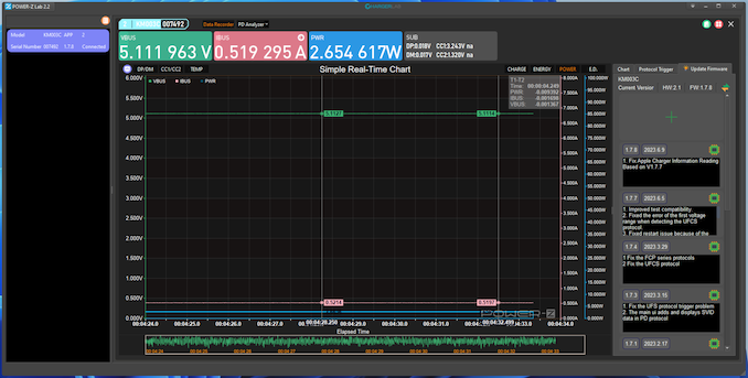
ChargerLAB provides a Windows application that can be used to manage multiple USB power testers from a single pane. Our evaluation was with a single KM003C in the list, which is displayed on the left in the interface. The application starts up with a ‘Data Recorder’ view. The top part of this view has all the parameters present in the on-device screen’s dashboard interface, while the bottom part has a real-time chart (with the available parameters on either side of the title). On the right side, a button to trigger the chart updates is available. The sampling rate can also be adjusted. Available rates are 1, 10, 50, and 1000 samples per second. The cache depth on the PC side is also configurable.
The software interface language can be modified from the triangular drop down on the top right near the window controls. However, some options continue to remain in Chinese even after the language is set to English. However, the software is intuitive enough for that to not be too much of a concern. The device firmware, as well as the application itself, can be updated from within the program. The ‘PD Analyzer’ view shows a real-time view of the various voltages and currents, along with a tabular view of the PD handshake process. Various other options such as saving graphs, recording data to a CSV or SQLite DB on the PC, etc. are available, as shown in the gallery above.
Open APIs
The Windows application is closed-source, but ChargerLAB provides some documentation in their HID Demo archive. The document is in Chinese, but I used Google Translate to get an inkling of the contents. From previous reviews, I have found that links often go stale. In order to avoid that with the KM003C API description, a screenshot of the translated version is provided below.
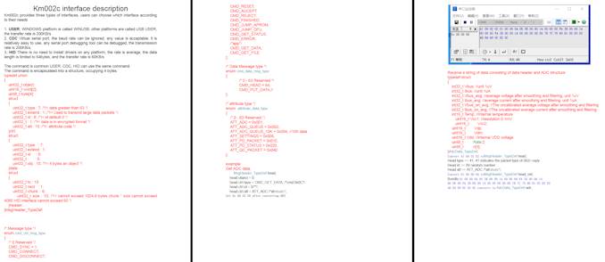 Click for a higher-resolution version of the API document
It is possible that ChargerLAB might update the APIs in the future. In that case, the latest version can be obtained from the FAQ section on their support page. ChargerLAB states there are three interfaces available – as a WinUSB (vendor specific interface) device, a HID device, or a virtual serial port (CDC). The next couple of sections take a look at how these interfaces can be taken advantage of in different operating systems.
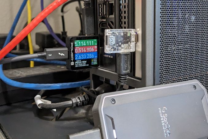
Our current USBC-TKEY-based setup for measurement of power consumption uses a Ubuntu 20.04 machine for tracking the parameters on the VBUS line. Since the USBC-TKEY has a command line interface accessed over the serial port, we had developed a Python script to record a CSV file with the required data. In order to experiment with the APIs provided by ChargerLAB for the KM003C, a SanDisk Professional PRO G40 Thunderbolt 3 portable SSD was connected to a Thunderbolt 3 port of a Quartz Canyon NUC with the KM003C acting as a man-in-the-middle (additional details in a later section discussing the KM003C in action). The HID port of the KM003C was connected to the Ubuntu machine using a Type-C to Type-A cable.
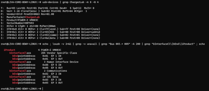
The API document makes a note of the KM003C presenting itself with three bidirectional interfaces. As only Windows support is claimed, it is no surprise that only the HID endpoints get exposed via the usbhid driver. The WinUSB endpoints belong to a vendor specific class, and the virtual serial port appears as a CDC data interface.
In exploring the KM003C as an alternative to the USBC-TKEY, we wanted to retain the Python script infrastructure (because it tied in well with the other components of our direct-attached storage evaluation infrastructure). It turned out that Python’s libusb module could act as a WinUSB alternative with its ability to access the endpoints under the Vendor Specific Class. This module requires the end user to be aware of the raw data that needs to be sent across the interface, and the format in which data is returned on the other endpoint.
The relevant modules to import in Python3 for libusb support are usb.core, usb.util, and usb.control. Since the vendor and product ID of the KM003C are known from the output of the usbdevices command, they are used directly to open the device for access through the script. Reliable scripting needs to ensure that the device is successfully found. For demonstration purposes, the variable contents are displayed, as shown above.
While the libusb module aims to be cross-platform, we did find that the steps below to detach the kernel driver did not work on Windows. libusb needs exclusive access to all the interfaces over which communication is expected to take place. For demonstration purposes, the code extract above cycles through a hard-coded number of interfaces (4), but it is possible to obtain that number from other functions in the module. The extract checks if an interface has a kernel driver attached to it, and detaches it in that case. It then proceeds to claim the interface for access through the script’s session.
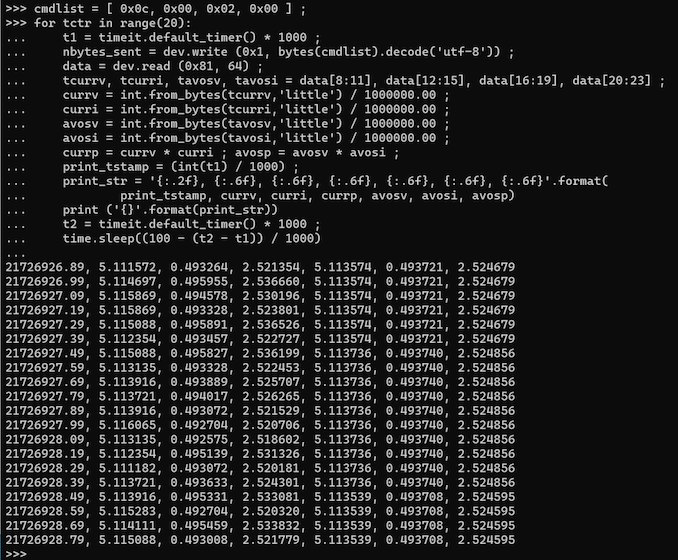
In order to retrieve the power consumption data from the device, a command needs to be transferred via the EP 1 OUT endpoint (with endpoint address 0x01). As ChargerLAB mentions, we can also use the EP 5 OUT and EP 3 OUT ones at addresses 0x5 and 0x3, but the response needs to be monitored at the corresponding EP IN endpoint. The command itself is in the form of a 32-bit word, and its encoding is detailed in the API document. In the script extract below, the 32-bit word is 0x0C000200. It corresponds to a GET_DATA command for the ADC data with a command ID of 0x0. I found during the course of experimentation that the ID in [23:16] could be varied from 0x0 to 0xFF without any loss in functionality. Since the command remains the same throughout the reading loop (we attempt to read out the power data 20 times with a gap of 100ms between each read), the command word is initialized outside the loop.
The first step in the loop is to obtain a timestamp for the command written out to endpoint address 0x1. This write is followed by the read to endpoint address 0x81 (the EP IN corresponding to the EP OUT used in the write). The read is blocking, i.e, it waits for the data to be sent back by the device and there is a default timeout associated with this command. The received data is then parsed out into appropriate components (instantaneous VBUS voltage and current, and the averaged VBUS voltage and current) based on the struct specified in the API document.
The HID demonstration code (supplied as a Visual Studio 2019 project) tagged along with the API document read out the averaged voltage and current. The documentation did not specify the averaging duration or the sampling rate. In the initial trials, the code did not read out the instantaneous values, and I was left frustrated as to why the averaged value was changing only once every second instead of getting updated for every read out. I spent quite a bit of time trying out the same code with different endpoints, and even different OSes. I even went to the extent of using Wireshark along with usbpcap in an attempt to trace the commands sent and data received by ChargeLAB’s closed-source Windows software. It was only after careful analysis of the packet capture did I realize that the average VBUS voltage and currents were changing only once ever second even in the traffic triggered by the software. The instantaneous data of interest actually turned out to be the first two words in the returned ADC data struct. The time taken for the read process and display of the CSV data is computed and the code segment is left idle before starting the next loop iteration 100ms later. Each line in the output data stream shows the timestamp, instantaneous voltage, instantaneous current, and instantaneous computed power, followed by the averaged versions of all three. Given the details of the averaging process, it is possible that the computed averaged power consumption can also be interpreted as the energy consumed by the sink (device, in this case) since the last change in that parameter.
As a final step in the script, a cleanup is performed so that all open accesses to the device via libusb are flushed out, and the device is made accessible to other programs. The script can then be terminated safely.
Custom user programs and scripts to access the data from the KM003C are comparatively easier to create on Windows compared to Linux. One of the primary reasons is that ChargerLAB supplies a HID demo program (ZIP) on its technical support page. It includes a VisualStudio 2019 project with C++ source code to access the data from the device. The KM003C also presents itself as an USB device as well as a serial device to the OS. In the ideal case, we should have seen the latter interface even in Linux as /dev/ttyACM0, but that was not the case in our Ubuntu install.
Powershell is my preferred scripting language on Windows machines, and accessing the KM003C as a serial device is as simple as opening the appropriate COM device output in the above command. As mentioned in the API document, the baud rate and other parameters do not matter.
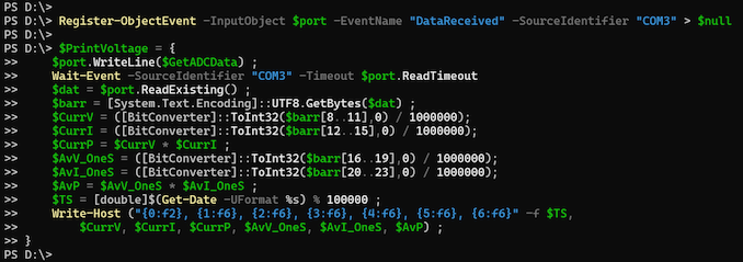
The command to be sent over the serial port for getting the ADC data (the 32-bit word, 0x0C000200) is prepared. Similar to libusb, the device write function expects a UTF-8 string. Unlike libusb, the read function is not blocking. In order to avoid polling for the data, or waiting for a pre-defined amount of time (by which there is no guarantee that the read might have returned the data from the device or not), a Powershell event is set up to trigger whenever data is received on the opened port.
The read out process is isolated out into a script block, and the logic to compute the instantaneous and averaged power consumption is similar to what was done using Python on Linux. The main difference is that we wait for the event triggered by the data receipt before the call to the read from the port.
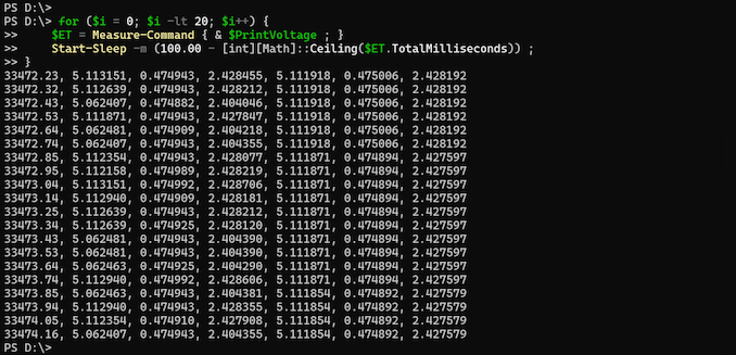
The script block is called in a loop every 100ms and generates output that is similar to the one created by the Python script in the previous section – CSV strings with a timestamp, followed by instantaneous voltage, current, and power, and the averaged versions of the same.
The clean-up process involves closing the port and deregistering / removing the event set up to track the data receipt from the port.
Prior to the adoption of the KM003C as a replacement for the tried and tested Plugable USBC-TKEY (Google Twinkie), we wanted to perform a few checks. Any inline power meter has the possibility of introducing signal interference that can adversely affect bandwidth (by introducing retransmissions). That is one of the primary reasons for almost all low-cost PD analyzers in the market to completely disable data transmission while monitoring the PD traffic.
The test setup for the KM003C involves one of the Thunderbolt 3 ports on the Quartz Canyon NUC – our direct-attached storage testbed. The SanDisk Professional PRO-G40 was chosen as the target device. A CrystalDiskMark run with a 32GB data span (five passes, and 12 distinct workloads, with each workload separated by 5 second intervals) was processed in three different setups:
- Direct connection to the Thunderbolt 3 host port without inline power metering
- Connection to the Thunderbolt 3 host port with a Plugable USBC-TKEY (Google Twinkie) acting as a man-in-the-middle (MITM)
- Connection to the Thunderbolt 3 host port with a ChargerLAB KM003C as a MITM
The three screenshots below show the CrystalDiskMark benchmark numbers obtained in each of the above three scenarios.
Though the vanilla configuration with no MITM comes out on top in all the workloads except for the high queue depth random writes, all the numbers are bunched close together within the realm of run-to-run variations. As such, the impact on the performance numbers with the KM003C is no different from the impact resulting from having the USBC-TKEY as an interposer.
Moving on to the recorded power consumption data, we first take a look at the numbers polled from the USBC-TKEY at 1 second intervals.
A peak of 7.16W was observed via the USBC-TKEY. From the Google Twinkie / USBC-TKEY documentation, it is not clear whether the ‘twinkie vbus’ command reports instantaneous numbers or averaged ones – but, looking at the smoothening, it does appear to be an averaged one.
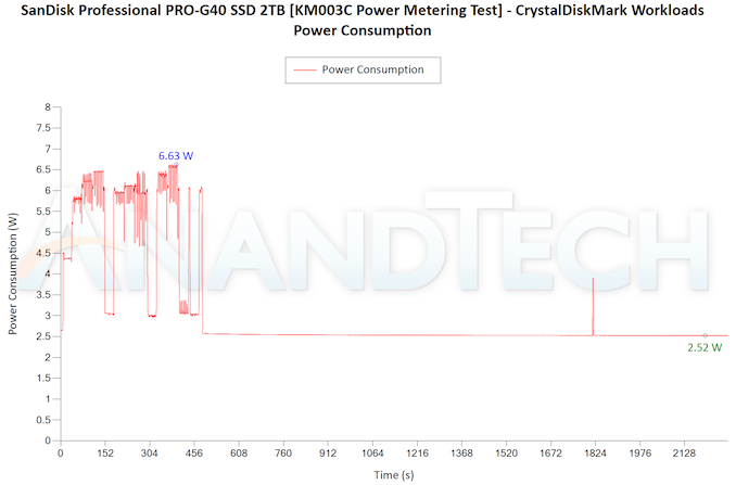
In the first pass with the KM003C, we attempted to retain the 1 second polling interval used with the USBC-TKEY. Recording the averaged power consumption made more sense in that case.
A peak of 6.63W is observed for the 1s polling interval, and the graph is quite smooth. This needs to be compared with the high-resolution graph (where the data is polled every 100ms, and the instantaneous values are recorded) having a 7.55W peak.
A 100ms polling interval seems to yield a better record of power consumption spikes. A better idea of the energy efficiency of a bus-powered device can probably be obtained by looking at the sum of the averaged power numbers throughout the duration of the test. For devices like portable SSDs, this will also take into account any deep-sleep idle timeout features and garbage collection activities. Overall, the KM003C appears to expose more interesting data compared to the USBC-TKEY for evaluation of the power and energy efficiency of bus-powered USB devices.
Our evaluation of the ChargerLAB KM003C for the purpose of USB-C power metering returned very good results, making it a credible alternative to the Plugable USBC-TKEY / Google Twinkie for our use-case. The hardware build quality is top notch, with the aluminum enclosure miles ahead of the flaky transparent polycarbonate shell enclosing the Twinkie PCB in the USBC-TKEY. The KM003C also comes with an aluminum box to store the device safely when it is not in use.
Most mainstream consumers opting to purchase the KM003C do it to ensure that their USB-C chargers are operating as expected and delivering the appropriate amount of power to the sink. Despite the emergence of USB-PD, many custom fast-charging protocols with varying voltage and current levels are also present in the market. The KM003C has the ability to recognize a large number of these custom protocols and give feedback to the user on the power at which a device is getting charged.
A search on Amazon reveals a large number of USB power meters, and a few of them like Plugable’s simple-to-use USBC-VAMETER3 are from reputed brands. However, most of the low-cost ones (including the Plugable model) just present the collected data on a screen built into the device. Only a few models allow for monitoring and processing the collected data externally, and very few actually provide APIs for this purpose. ChargerLAB’s KM003C belongs to that rare category, and provides API details as well as a demo program using those APIs. Additionally, very few allow high-speed data pass-through, and the KM003C and the Plugable USBC-TKEY / Google Twinkie are the rare exceptions that can support pass-through up to 40 Gbps.
One of the unique aspects of the KM003C is that its manufacturer (ChargerLAB) has been releasing frequent firmware updates to address bugs and add new features. They also maintain a technical blog detailing the features of the product. The posts serve as an introduction to some of the advanced features of the KM003C. On this front, ChargerLAB seems to be comprised of hardware enthusiasts who understand the needs of power users. ChargerLAB’s support team is also quite responsive. I had mailed them once prior to purchase (wanting to check whether the KM003C could be used as an alternative to the Google Twinkie / Plugable USBC-TKEY), and they helpfully pointed me to their transmission test blog post and the FAQ section in their technical support page. I also communicated with them about the sampling rate issue, but after a few days they could not come back to me with an appropriate answer (that I was looking up the wrong bits from the returned data structure). That said, the e-mail exchange was definitely on a much higher technical level than any of my previous tech support conversations with other vendors.
The KM003C is also relatively future-proof, and claims support for 240W PD measurement when adapters supporting that wattage are not even available in retail yet. The digital power monitoring chip is one of the primary components restricting the usage of certain USB power meters with higher wattage power supplies. Even though the USB-PD 3.1 protocol only goes up to 48V, the INA228 metering chip can withstand up to 85V (the KM003C is rated for 0-50V).
In terms of scope for improvement, the KM003C does have an outstanding issue with passing USB 2.0 traffic. While the product does come with an online English manual, the API description document is only in Chinese. A more detailed multi-lingual version would be nice to have. Allowing replication of functionality such as altering the settings and tracking charge / energy via APIs should also be included. The software accompanying the device has many features, but is not particularly stable (with the application terminating unexpectedly under some circumstances).
A replica of the on-device screen in the software would be nice to have for easier remote operation. A ‘Virtual Display’ tab in addition to the ‘Data Recorder’ and ‘PD Analyzer’ that replicates the on-screen contents along with virtual buttons to allow cycling through different options (just like physically operating the buttons on the device would) would make the user experience better. Often times, it is difficult to keep track of the behavior of each button in different screens. Being able to handle this from the software would make things much easier.
The features of the KM003C make it appeal to a wide variety of consumers. However, for specific use-cases like ours, features such as the on-device screen and physical buttons are not particularly useful. Allowing everything to be accessed and controlled via the HID port and removing the screen / buttons to reduce the BOM cost (and end-use pricing) in a KM003C-Lite would be a consumer-friendly move from ChargerLAB.
Overall, the ChargerLAB KM003C springs a pleasant surprise by providing capabilities that go above and beyond the claims in their marketing material. The core capabilities have been reviewed with good results by multiple outlets on YouTube. Since they are incidental to our primary use-case, we did not bother with testing those in detail. Our aim was to evaluate whether the KM003C would make a good relatively future-proof alternative to the Google Twinkie for power metering, and we are glad to report that the product passed the test with flying colors. There is some scope for improvement as outlined earlier in this section, and the product could do with some competition to drive down the pricing. The KM003C is available in China for around 400 RMB, which translates to around $55. On Amazon, the product is available for double the price – $110. Even accounting for import costs, the markup is a little hard to digest. Despite this premium pricing, we believe that the KM003C should be part of every USB-C power user / developer’s toolkit.
Post Disclaimer
The information provided in our posts or blogs are for educational and informative purposes only. We do not guarantee the accuracy, completeness or suitability of the information. We do not provide financial or investment advice. Readers should always seek professional advice before making any financial or investment decisions based on the information provided in our content. We will not be held responsible for any losses, damages or consequences that may arise from relying on the information provided in our content.


