


Abstract
An original fully textile combiner is proposed to power supply sensors close to a body with only one centralized source of energy like a smartphone, for instance. A solution is provided for taking into account the requirements of an industrial production process that need to minimize needle movements during an embroidery process. Moreover, the paper shows how to support several wireless power transmission standards that already exist, i.e. NFC and A4WP, or will exist to satisfy the tremendous needs of energy for distributed systems in the IoT domain. In this paper, a new textile-based flexible wireless system enabling communication and energy harvesting is proposed. Analytical, numerical, and experimental studies have been conducted to demonstrate that the structure has two resonant frequencies at 6.8? MHz and 13.6? MHz, which make it suitable for NFC and A4WP standards. Moreover, the losses caused by the system are 2.76? dB and 1.91? dB for A4WP and NFC, respectively. The results are successively presented to highlight the specificities of such textile multi-coils combiners. A method for gaining a resonant structure without any solid electronic component is explained.
Introduction
The connected textiles recent development enables the rise of data and energy transmission within clothing. Indeed, the embedded sensors in our cloth need a power supply to work and transmit data. Near-field Communication (NFC) technology is a solution to centralized energy sources and data storage, especially with the battery and memory capacity improvement. Progress in electronics has already enabled to use of wireless power transfer (WPT) between wearable small devices and smartphones, NFC technology equipped1,2. Some small IoT devices such as physiological sensors may require to be sometimes only power supplied, eventually by a technology standardized by the A4WP (Alliance for wireless power) recently re-named Airfuel (Air Fuel Alliance), knowing that the Qi technology is an alternative standard, that is already available on the market3,4,5. The latter technology has not been retained in the present work as it runs at very weak frequencies around 300? kHz which would restrict its usage to perfectly aligned and identical antennas for the transmitter and receiver located near the combiner. It is to be noticed furthermore that the frequency of the A4WP standard is exactly half of that of the NFC frequency.
Numerous energy sources can be used to power supply e-textile, but smartphones are today equipped with NFC antennas and can store, process, and send a large amount of data. Consequently, they are particularly adapted to the power supply and connect smart textiles to a different network. For example, an energy transmission system has been developed to power supply smart textiles from bicycle mechanical energy6. Jiang et al. have also developed a textile NFC antenna with silver-plated yarns able to transmit data even under flexions7. More recently, Rongzhou Lin et al. have also published a study presenting an integral textile NFC transmission system embroidered on a garment8. It aims to monitor real-time physiological parameters in a nomadic way, like during running. However, the device needs a few rigid electric components to work and its operating frequency is not adjusted to 13.56? MHz. Another study on textile NFC antennas focused on the resonant frequency aspect9. It shows that the embroidered antenna can be realized only with textile materials and processes, and its resonant frequency can be adjusted to the NFC technology. Finally, the association of several textile antennas can create new devices, called ?EURoecombiners?EUR?, enabling to transfer of a 13.56? MHz magnetic field through a textile surface10. Unfortunately, this kind of structure includes a soldering point to close the circuit, which produces a weakness in the device. There are also textile near-field multibody area network structures used for on-body communication developed by metamaterials built from arrays of discrete, anisotropic magneto-inductive elements11. Unlike the results published in recent articles on that topic, our work proves the possibility to communicate and transfer energy following two different wireless standards (NFC and A4WP) without any traditional electronic component. Only the textile material and processing techniques are used to design and produce the antenna and combiner.
Compared to the previous structure10, the soldering point has been replaced by a textile capacitor. First, a theoretical study of the structure highlights the presence of two resonant frequencies reliant on the antenna’s intrinsic resonance and the value of the new textile capacity, respectively. Second, simulations have been conducted to evaluate the structure’s electrical responses. Third, the transmission coefficient S21 has been measured to identify the experimental resonant frequencies. Finally, a practical application has been realized, as a proof of concept.
Materials and methods
Textile dual-band near field multiple combiners
The textile dual-band (NFC-A4WP) combiner enables to transfer of energy and data across clothing at two different frequencies, 13.56? MHz and 6.78? MHz, by using successive magnetic induction couplings. The device is composed of several antennas that can be used as a transmitter or a receiver. All antennas are identical and composed of a 40? mm, 10 turns coil, connected to a 130? mm transmission line, as shown in Fig.? 1a, b. They are associated symmetrically, to form a circuit composed of a single current line with an embroidering process. Two current lines, with variable lengths, are added to the embroidery start and end. A picture and a diagram of the device are shown in Fig.? 1c, d. The current line is formed by using three overlapped textile conductive yarns Datatrans, from Tibtech Company.
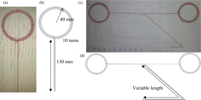
(a) Photography of the antenna and (b) its diagram. (c) Photography of the two antennas textile dual-band (NFC-A4WP) combiner and (d) its diagram. Figure? 1(b) and (d) were carried out using Inkscape software v1.2.2 (https://inkscape.org/).
The antenna’s electrical characteristics are already known from previous studies9,10. A Textile dual-band (NFC-A4WP) combiner with two of these kinds of antennas has been prototyped to evaluate its transmission coefficients. Also, the length of the current lines at the start and the end of the embroidery and forming a section of the parallel transmission line is variable to study its impact on the resonant frequencies and the transmission coefficients.
Theoretical electrical characteristics
Textile dual-band (NFC-A4WP) combiner and its electric diagrams are presented in Fig.? 2a, b, with L as the inductance, C as the capacity of one antenna, R as the coil resistance, and r as the transmission line resistance. Copen is the capacity of the additional open-ended section of the transmission line, called AOETL in the rest of the paper, with a variable length forming the start and end of the embroidery. Assuming one of the coil antennas is excited by inductive coupling, the circuit impedance viewed by the induced voltage source (not shown in Fig.? 2) can be expressed by the Eq.? (1) where ?? is the pulsation of the sinusoidal signal and j is the square root of ?^’?EUR?1.
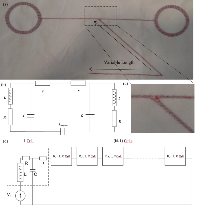
(a) The two antennas textile dual-band (NFC-A4WP) combiner, (b) its electric diagram and (c) a zoom on the opening capacity Copen. (d) Case of an N-coils combiner (cells) inductively excited (inductive voltage source).
Although Fig.? 2b shows a 2-coils combiner, the following analytical study gives more generalized equations adapted to an N-coils combiner (1 input, (N-1) outputs) as depicted in Fig.? 2d. Each antenna is modelled by a cell with r, R, L, and C parameters already defined in the 2-coils combiner case. The left antenna is inductively coupled to a not shown transmitter resulting in the presence of a voltage source Vi. Thus, the impedance Zi viewed by the source is given by the following equation:
The resonance conditions are obtained when the imaginary part of the impedance vanishes. The Copen capacity being in series with a sum of parallel resonant circuits (coils) may bring a new resonant frequency in addition to the initial resonance coming from the antennas12, except for two simplified scenarios that have been analytically studied. First, the case where the circuit resonates only at the proper frequency of each antenna. Then, the case where the capacity of Copen is very small compared to the specific antenna?EUR(TM)s capacities. In each case, the conditions that enable the influence of this opening to be neglected will be emphasized. They are obtained when the impedance fed into the circuit is negligible compared to the modulus of the impedance, denoted Z?EUR(TM), of the N-1 antennas connected in series with it.
The impedance provided by Copen and by the (N-1) antennas connected in series are respectively given by the following expressions:
Post Disclaimer
The information provided in our posts or blogs are for educational and informative purposes only. We do not guarantee the accuracy, completeness or suitability of the information. We do not provide financial or investment advice. Readers should always seek professional advice before making any financial or investment decisions based on the information provided in our content. We will not be held responsible for any losses, damages or consequences that may arise from relying on the information provided in our content.
